Industry Applications | Charging Piles and Energy Storage Liquid Cooling: From "Able to Cool Down" to "Capable of Large-Scale Delivery" (Part 1)
Introduction: From “Cooling Capability” to “Deliverable Systems”

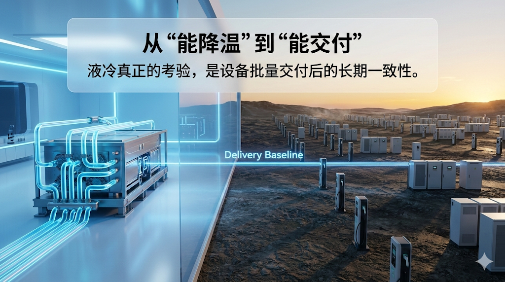
The real difference between liquid cooling solutions often does not lie in their cooling performance during the design phase, but in their consistency and maintainability after deployment.
High-power charging stations, energy storage converters (PCS), and power cabinets are rapidly moving toward higher power density. Thermal management is increasingly becoming a system-level engineering challenge, and liquid cooling is gradually becoming a standard configuration for high-power equipment.
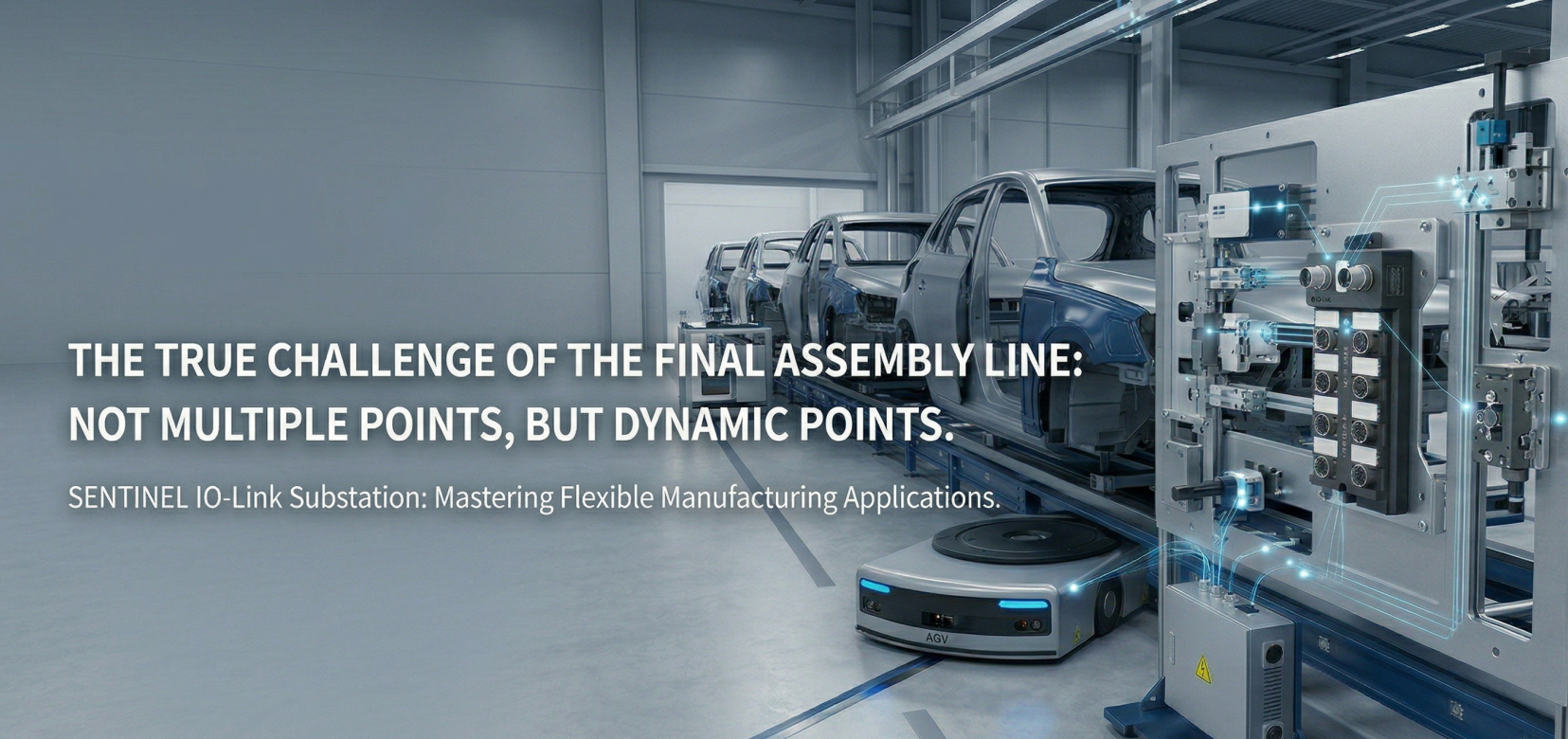
However, in real projects the true test of a liquid cooling system is rarely whether it can pass a full-load test once. The real challenge lies in its long-term consistency after large-scale deployment. When the same solution is installed at different sites, under different ambient temperatures and maintenance conditions, can it still operate reliably? When an alarm occurs on site, can technicians quickly locate the problem without dismantling pipelines or draining coolant? After replacing components, can parameters and thresholds be restored to their original factory state quickly?
These applications share a typical constraint: distributed deployment, outdoor environments, and limited on-site personnel. For equipment manufacturers, the quality of a liquid cooling system is ultimately reflected in metrics such as downtime rate, service costs, response time, and long-term customer perception of reliability. In many cases, the true performance of a liquid cooling solution is better revealed in the field than on a laboratory test bench.
Core Insight: Three Essential Capabilities
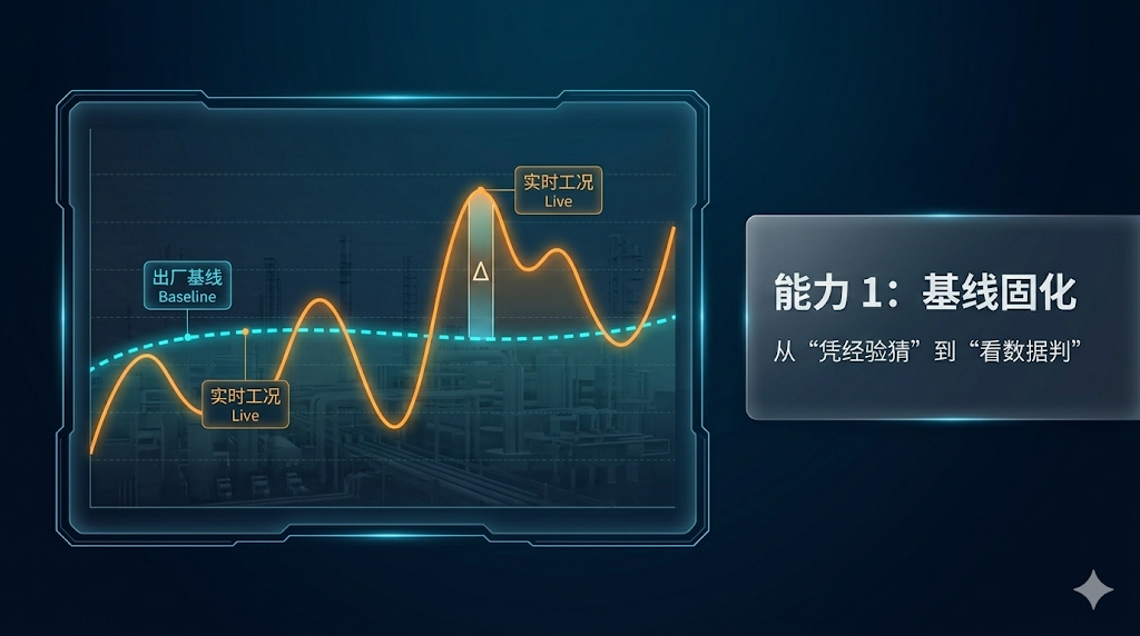
1. Baseline Solidification. Before equipment leaves the factory, the key operating states of the cooling loop should be recorded as a traceable baseline curve — including flow, pressure, and temperature under stable conditions. During operation, any deviation from this baseline can immediately narrow down the troubleshooting scope, transforming fault diagnosis from experience-based judgment into data-driven analysis.
Without a baseline, it becomes difficult to determine whether an abnormal condition is caused by operating conditions or by a developing fault. When a user reports that “temperature is higher than usual”, engineers might need to check dozens of parameters before identifying the cause. With a baseline, maintenance personnel can directly compare current data with the original operating curve, making troubleshooting far more efficient.

2. On-site Visibility. In outdoor environments, maintenance teams cannot always rely on complex diagnostic tools. Key measurement points must provide information that can be understood directly at the equipment side.
The ability to quickly distinguish between conditions such as “no flow”, “increased resistance”, or “reduced heat exchange efficiency” through flow indicators, pressure readings, and temperature displays directly determines troubleshooting efficiency. Without clear on-site visibility, technicians can only rely on experience, which increases diagnostic time and the risk of misjudgment. This is one reason why service costs remain high in many systems.
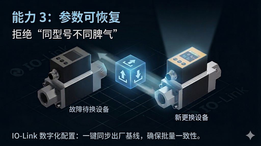
3. Parameter Recoverability. Large-scale deployment fundamentally means replication. Replication requires consistent parameters. After replacing sensors, valves, or pumps, thresholds, output logic, and alarm windows must be restored quickly to avoid hidden inconsistencies between identical devices.
Without reliable parameter recovery, each installed unit may gradually behave differently. Over time, this increases service complexity and may even lead customers to believe that product quality is inconsistent, when the real issue is simply parameter drift.
These three capabilities support each other: the baseline provides the reference, visibility provides the diagnostic path, and recoverability ensures maintainability. Missing any one of them makes large-scale deployment significantly more difficult.
Building a Measurement Architecture: From Baseline to Recovery
Engineering delivery of liquid cooling systems requires transforming scattered measurements into a structured monitoring architecture. This architecture can be divided into three layers.
Bottom Layer: Standardized Sensors and On-Site Visibility
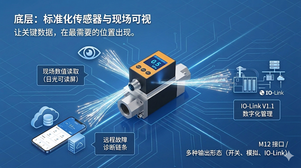
The key to on-site visibility is not simply adding larger displays, but ensuring that critical data appears exactly where it is needed.
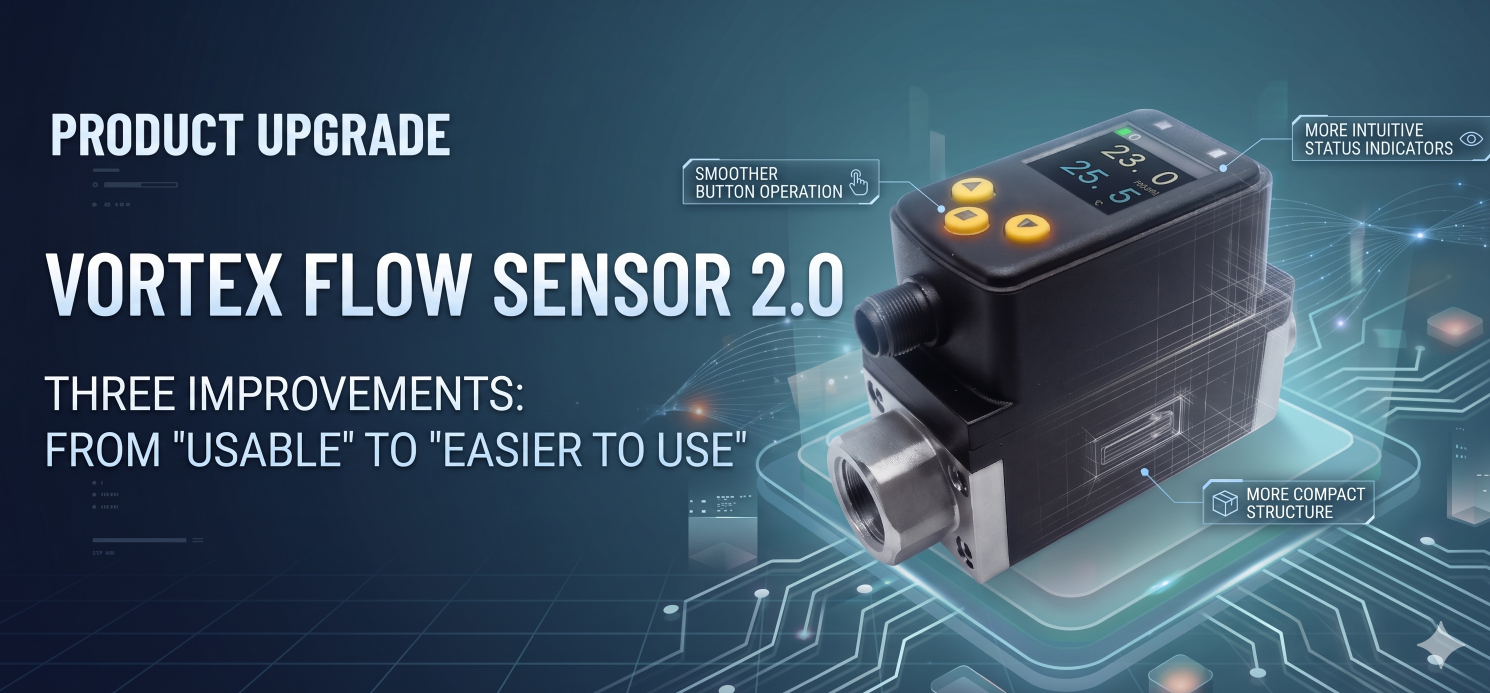
On the flow side, thermal flow switches can cover common flow ranges in both water and oil media. Adjustable switching points and status indicators allow quick on-site checks. For distributed applications such as charging stations and energy storage systems, these “baseline protection” devices significantly reduce false service calls and unnecessary field visits.
Pressure and temperature monitoring require more than simple switching signals. Sensors with integrated displays allow technicians to directly read numerical values on site. With robust M12 metal connectors and IP67 protection, these sensors also support deeper parameter management through the IO-Link V1.1 protocol.
Their multiple output options — switching signal, analog signal, and IO-Link communication — allow alarm handling, trend monitoring, and system integration to be achieved within the same measurement point.
Well-designed field-visible devices typically share several characteristics: rotatable electronic housings for flexible installation, parameter setting through push buttons or IO-Link without special tools, and displays that remain readable even under direct sunlight. These seemingly small details often determine real maintenance efficiency in distributed deployments.
Middle Layer: Hierarchical Alarm Logic
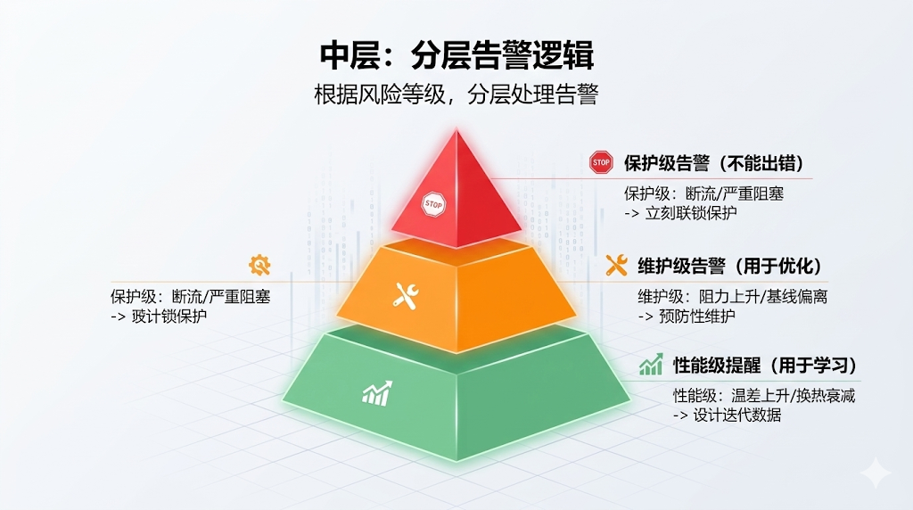
A common mistake in many liquid cooling systems is treating all abnormal events with the same level of severity. Proper engineering practice categorizes alarms according to risk level.
Protection-level alarms address critical issues such as loss of flow, pump dry-running, or severe blockage. These events require immediate interlocking responses because continued operation could damage equipment or cause significant power derating.
Maintenance-level alarms deal with developing issues such as filter clogging or gradual pressure deviations from baseline. These events do not require immediate shutdown but should provide maintenance teams with sufficient warning time to schedule preventive service.
Performance-level notifications record long-term trends such as increasing temperature differences or slowly declining heat exchange efficiency. Their value lies in design optimization and operational insight rather than immediate action.
This hierarchical alarm strategy prevents unnecessary shutdowns while ensuring that real risks are addressed in time. In many systems, layered alarms can reduce unnecessary service tickets by more than half.
Top Layer: Parameter Consistency
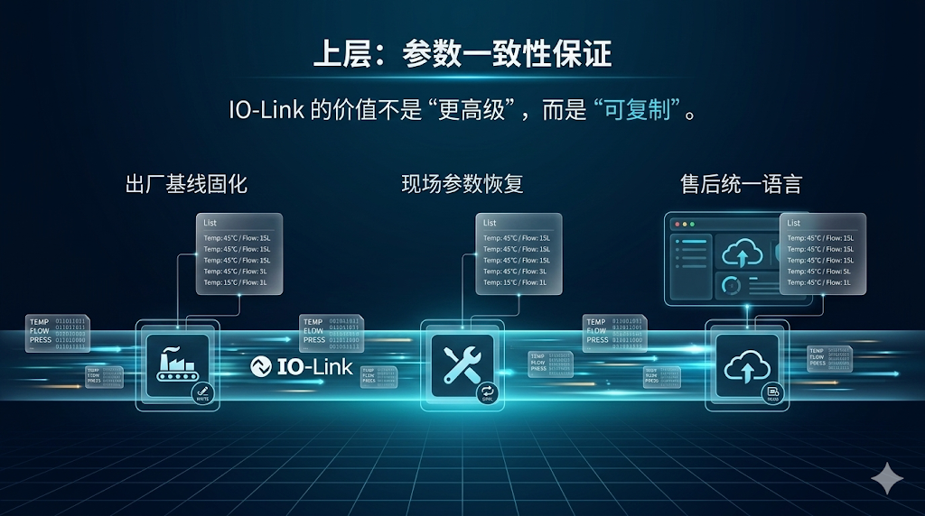
Within an IO-Link architecture, parameter recovery becomes a standardized process. During production, the same set of parameters — temperature thresholds, pressure limits, flow switching points, and alarm delays — can be written once and stored as the factory baseline.
During maintenance, when components are replaced, parameters can be quickly restored through IO-Link communication, ensuring consistent behavior between old and new devices.
For equipment manufacturers, the real value of IO-Link is not simply advanced communication, but reproducibility. The same parameters can be written in production, restored during maintenance, and interpreted consistently across service systems. This small change significantly reduces long-term service variability.
These three layers are interdependent: sensors provide data, alarm logic interprets the data, and parameter consistency ensures system reproducibility. Together they form the foundation for scalable deployment.
Why This Architecture Is Difficult to Replicate
Interestingly, although this system architecture appears straightforward, it is rarely implemented completely in practice. The main challenge is not technological complexity but a shift in engineering mindset.
Many liquid cooling solutions are designed purely from an R&D perspective: engineers determine which sensors to use and what thresholds to set, and then these decisions are directly applied to production and field deployment.
While this approach may work technically, it overlooks a key question: will these parameters, alarms, and measurement points remain effective when deployed across hundreds of sites and maintained by hundreds of technicians?
Large-scale deployment exposes these challenges. Parameters validated in laboratories may behave differently under varying environmental conditions. Alarm thresholds that seem reasonable may generate frequent false triggers under specific operating scenarios. Measurement points that are technically correct may still fail if maintenance personnel cannot interpret them easily.
For this reason, the three capabilities — baseline solidification, on-site visibility, and parameter recoverability — should be treated as fundamental design principles rather than optional improvements.
FAQ
What does baseline solidification mean?
Before delivery, the normal operating curve of flow, pressure, and temperature is recorded. During operation, deviations from this baseline help quickly determine whether changes are caused by operating conditions or developing faults.
Why is on-site visibility necessary?
Charging stations and energy storage sites are widely distributed and rarely staffed. Technicians must be able to quickly understand system status directly on site — whether the issue is loss of flow, increased resistance, or reduced heat transfer.
What is parameter recoverability?
After replacing components, thresholds, logic, and alarm windows must be restored quickly to maintain consistent behavior. IO-Link enables this process through standardized parameter storage and transfer.
Next Step
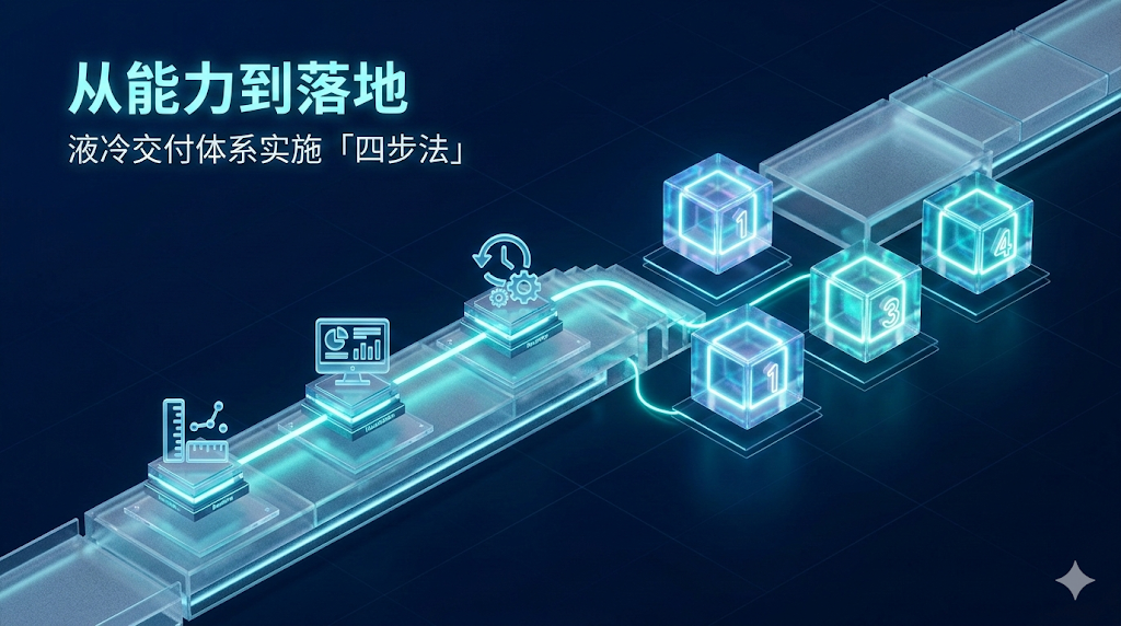
Once this architectural framework is established, the next challenge is implementation: standardizing commissioning procedures, simplifying on-site troubleshooting methods, and closing the maintenance loop.
In the next article, we will explore how to implement these concepts in real projects, including four key engineering steps and a complete deployment case of a liquid-cooled ultra-fast charging unit.
Customer Support and Service
Tianjin Sentinel Electronics has been deeply engaged in industrial automation for 17 years, providing more than 170 application cases across industries such as rail transit, automotive manufacturing, and new energy.
We offer full-cycle services ranging from sensor selection and system integration to after-sales diagnostics. For more information about Sentinel products, please contact our sales team or call +86-22-83726972. You can also visit our website at www.sentinel-china.com.
Schedule an online demonstration or request sample testing, and let our engineers help you build a complete solution from “data acquisition” to “actionable control”.