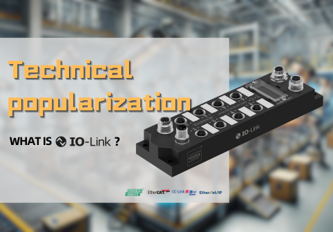
SENTINEL IO-Link Device Series Guide | Substations and Converters: Standardized and Unified Field Signal Access
Introduction: Understand the Aggregation Layer First to Avoid Detours in Upgrades
On the production line, the biggest time cost often isn’t about whether the algorithm can work, but about the “last meter” between the device and the control system. A large number of cables, inconsistent signal types, compact interfaces, and limited installation space mean that any process change may lead to rewiring and repeated debugging.
The value of IO-Link lies in integrating end devices into a unified, parameterizable, and diagnosable digital channel. The key to stable operation of this channel lies in the “aggregation layer” — namely, whether the design of substation and converter structure, interface configuration, and signal processing capabilities are reasonable.
Based on SENTINEL’s current products, this article systematically introduces how to standardize on-site signal access from three perspectives: layout design, signal types, and functional levels — providing engineers and procurement teams with a clear path for product selection.
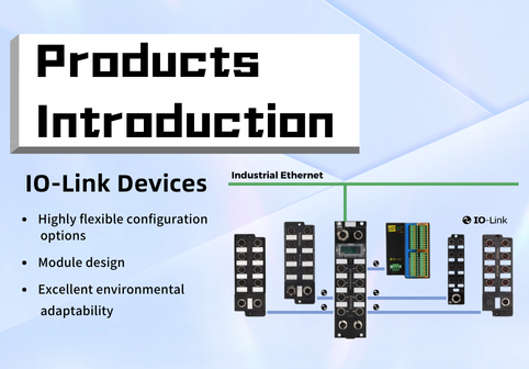
Layout and Interfaces: From Control Cabinet to On-Site Deployment
For legacy system upgrades, if devices are concentrated within a control cabinet, terminal-style (IP20) substations can be selected to achieve high-density wiring inside the cabinet, clear labeling, and easy maintenance and auditing.
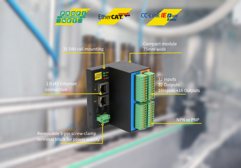
If proximity to the device is needed to shorten branches and reduce cable ducts and connectors, field-type substations should be selected. Among them, M8 models are suitable for high-density, space-constrained scenarios, while M12 models feature robust structure and reliable connections, ideal for most industrial environments.
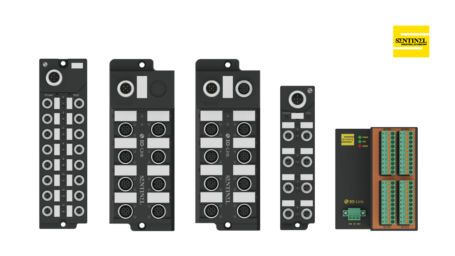
SENTINEL maintains consistent interface logic across product series. Take a typical M12 field substation as an example:
- Left side features a standard M12 A-coded (male) communication port for IO-Link communication and system integration;
- Right side includes three interfaces:
- M12 A-coded (male) — for low-current load power supply;
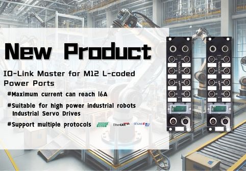
- M12 L-coded (male) — for high-current load power supply (up to 2 A per point);
- M12 A-coded (female) — for cascading additional substations.
The panel includes only POWER and RUN indicator lights:
- POWER shows power status;
- RUN shows communication status (running/offline).
This minimalist design ensures status is easily visible even under strong light, dust, or oil mist, reducing misjudgments and unnecessary troubleshooting.
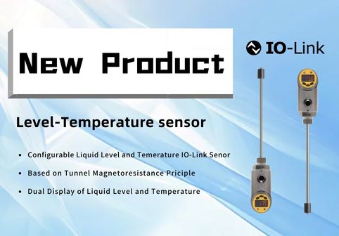
Signal and Channels: Unified Access for Digital, Analog, and Temperature Signals
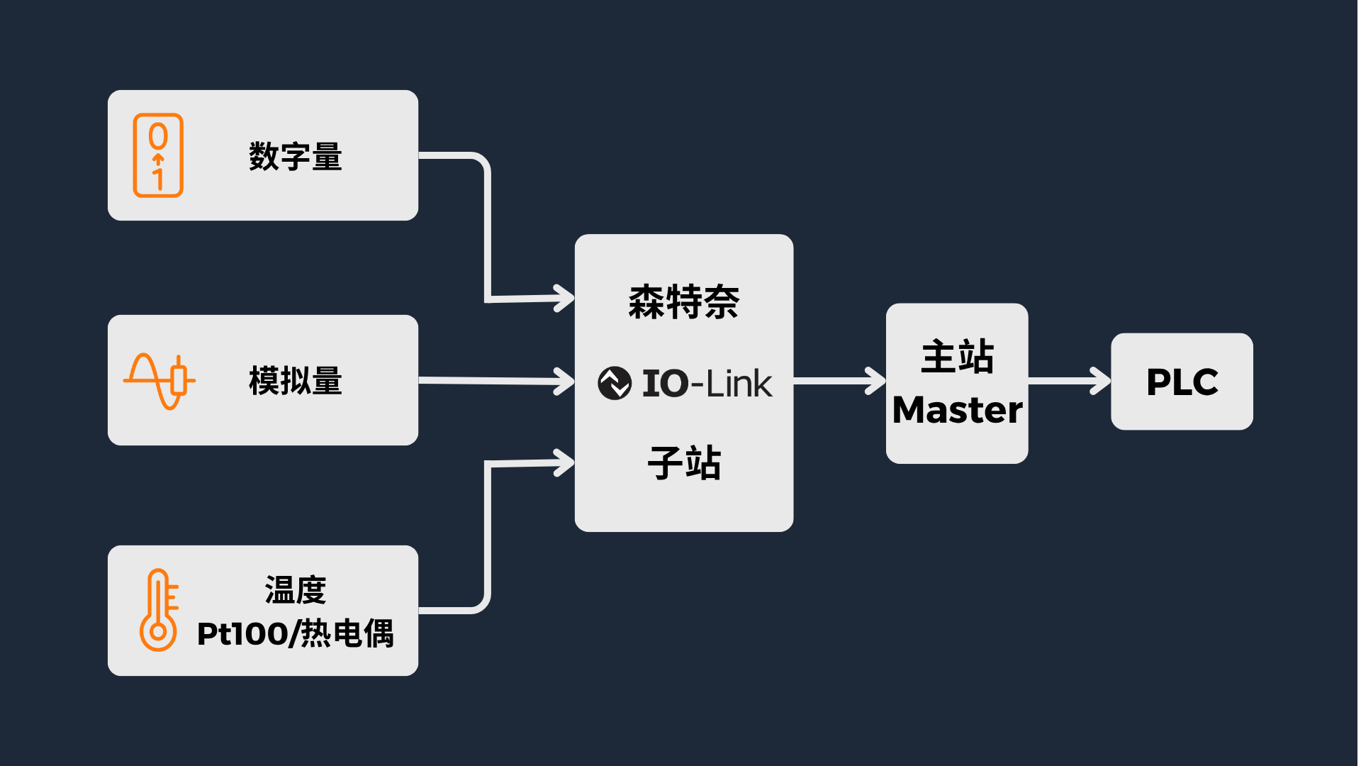
The complexity of field signals lies not just in quantity, but in diversity. SENTINEL substations cover three major signal types at the channel level:
- Digital I/O (DI/DO): For discrete tasks such as position detection, start/stop, and sorting. Each channel features current limiting and fault indication for quick localization and isolation of short circuits or miswiring.
- Analog I/O (AI/AO): Supports both 4–20 mA and 0–10 V standards. Ranges, refresh rates, and diagnostic data are transmitted uniformly to the upper-level system, facilitating trend monitoring and threshold configuration.
- Temperature signals (Pt100 / thermocouples): Input channels support linearization and cold-junction compensation, with anti-interference design, allowing temperature data to be managed alongside other process values within a unified framework.
This unified access architecture allows different signal types to be integrated via the IO-Link protocol, enabling parameterization, diagnostics, and replicable management.
Function and Flexibility: Gradient Selection from Fixed to Adaptive to Scalable
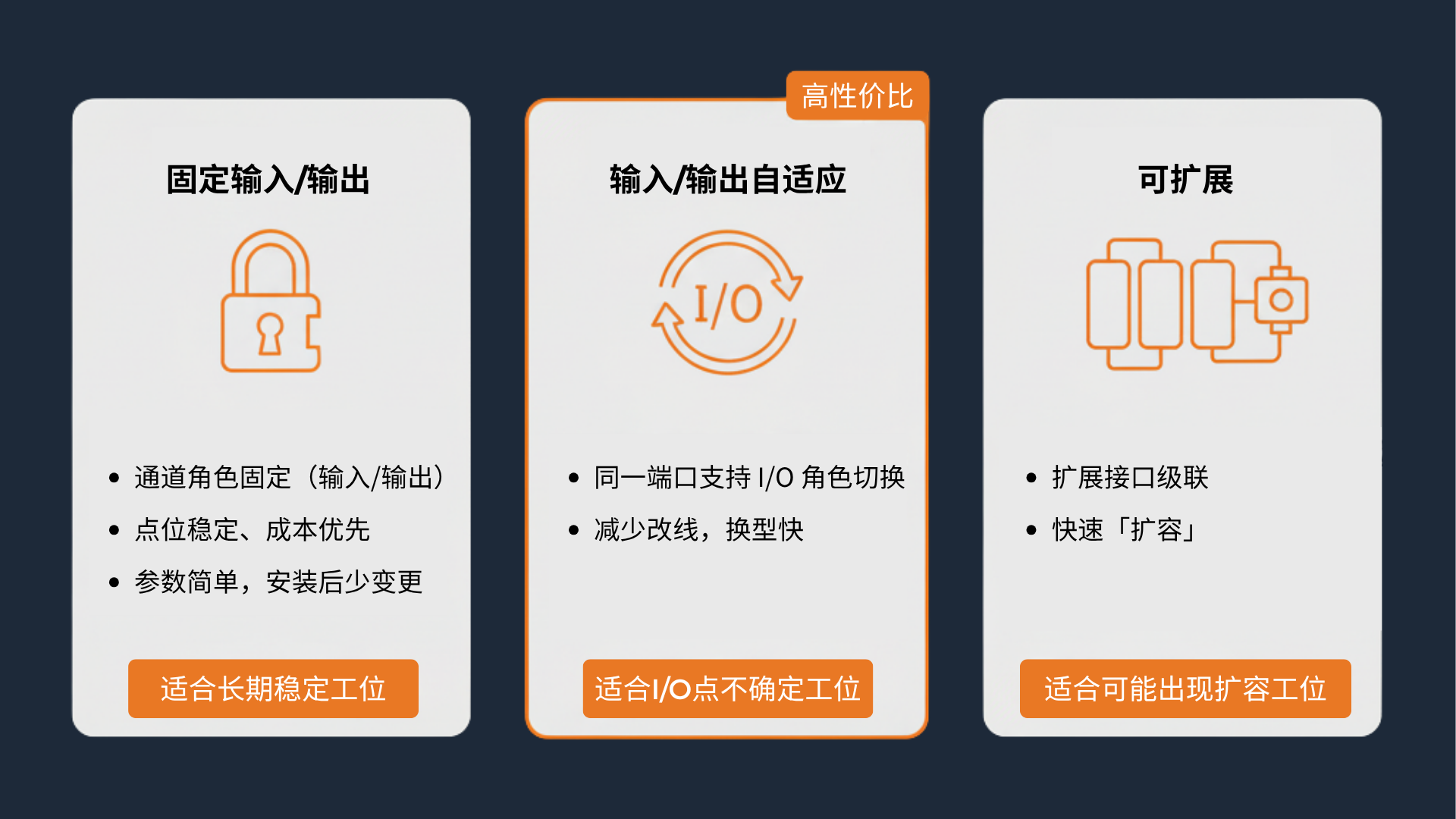
Structure and signal types determine whether a device “can connect,” while functional tiers determine whether it’s “easy to use after connection.” SENTINEL offers three functional levels:
- Fixed I/O: Channels have fixed roles, offering simple structure and low cost — suitable for environments with stable signal points.
- Adaptive I/O: Ports can switch between input and output; wiring and terminals remain unchanged. PNP/NPN/push-pull logic can be parameterized — ideal for flexible production lines with frequent product changes.
- Scalable structures: Additional substations can be cascaded via the M12 A-coded (female) extension port, enabling expansion or zoned access. Only data mapping needs to be added in the program — no rewiring or reconfiguration required.
Choosing the right function level should be based on the frequency of field changes and system flexibility needs. The more you pursue quick switching and flexible layouts, the more adaptive or scalable models should be prioritized.
Reliability and Protection: Building Stability into the Hardware
Flexibility does not mean compromising on reliability. SENTINEL employs a “zonal limitation” design at the power and channel levels to minimize the impact of faults.
A typical 12-port substation divides 8 I/O channels into two power domains: if one channel short-circuits, only its group is powered down, while the other continues running. Logical and load power are physically separated to prevent large transient currents from affecting communication.
Clear interface roles:
- Left A-coded (male) for communication;
- Right A-coded (male) and L-coded (male) for low and high current respectively;
- A-coded (female) for cascading extension.
Together with the POWER/RUN indicators, engineers can quickly assess “power status” and “communication status” even in high-noise, high-intensity environments, significantly improving troubleshooting efficiency.
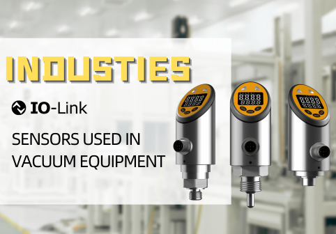
The Role of Converters: Bringing Traditional Signals into IO-Link
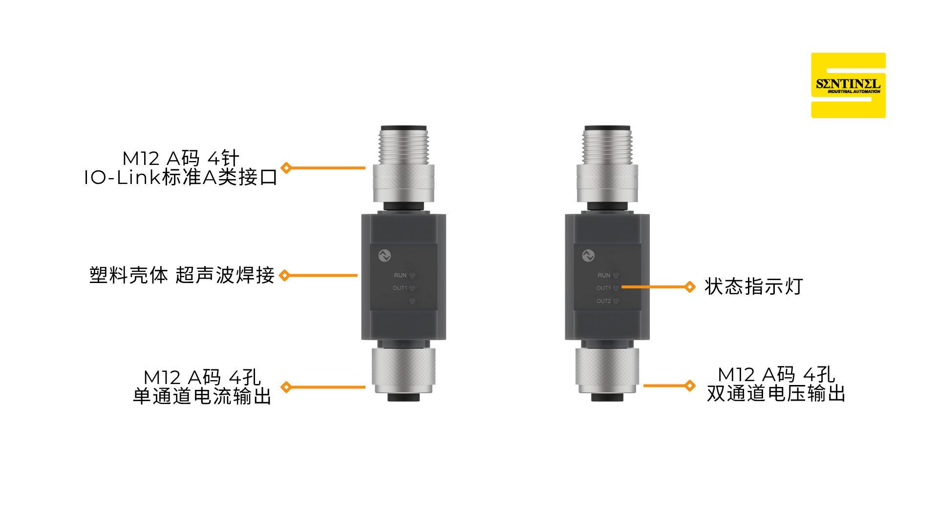
In on-site upgrades, you’ll often encounter equipment still using 4–20 mA, 0–10 V, Pt100, or thermocouple signals. SENTINEL’s IO-Link converters allow these analog or temperature signals to be integrated into the IO-Link network for digital management.
Converters come in two types:
- Input type: Includes single-channel Pt100, dual-channel 4–20 mA/0–20 mA, and dual-channel 0–10 V.
- Output type: Includes single-channel 4–20 mA/0–20 mA and dual-channel 0–10 V.
Introducing converters consolidates parameter, diagnostics, and replication operations — previously scattered across modules and software — into the IO-Link system. This enables faster on-site replacement and reset, and greatly reduces training and handover costs.
Selection Guide
- Clarify the Purpose
- Substations: For aggregating digital, analog, and temperature field signals;
- Converters: For converting 4–20 mA, 0–10 V, Pt100/thermocouple signals to IO-Link.
- List All Signals: Record each signal’s type, quantity, range/threshold, refresh rate, load capacity, and installation environment (temperature, humidity, EMI, etc.).
- Determine Form Factor and Protection Rating
- For centralized cabinet access: choose terminal-style (IP20);
- For device-proximal access: choose M8/M12 field type, depending on space and mechanical strength.
- Choose Function Type
- Fixed I/O: Stable points, cost-effective;
- Adaptive I/O: Requires port role switching;
- Scalable type: For cascading or multi-station duplication.
Conclusion and Call to Action
A well-designed “aggregation layer” is fundamental to a stable system. SENTINEL’s IO-Link substations and converters offer unified interface logic, signal architecture, and functional tiers — helping engineers reduce wiring and uncertainty during upgrades, and making it easier for procurement to consolidate models and optimize inventory.
For a complete selection table or on-site topology diagram, feel free to contact SENTINEL’s technical team. We can provide an implementation plan with minimal rewiring and fastest deployment based on your device list.
Stay tuned for the next article: “SENTINEL IO-Link Device Series Guide (Part 2) | Sensors and Relay Modules: Closing the Loop from Data to Action.”